
The pursuit of high-performance motion control in applications such as aerospace robotics and precision instrumentation has consistently driven the advancement of harmonic drive gear technology. Renowned for their exceptional compactness, high reduction ratios, and superior positional accuracy, harmonic drive gears rely on the controlled elastic deformation of a flexible spline, or flexspline, induced by a wave generator. The quality of meshing between the flexspline and the fixed circular spline is fundamentally dictated by the accuracy with which this deformation is modeled and translated into conjugate tooth profiles. Achieving a true zero-backlash condition, which is critical for precision, requires an exact kinematic solution that avoids the simplifying approximations prevalent in traditional design methods. This work presents a rigorous mathematical framework for determining the exact conjugate tooth profile of the circular spline, using an elliptical cam wave generator as a case study. The methodology is applied to a common double-circular-arc tooth profile, and its superiority over conventional approximate algorithms is demonstrated through comparative analysis of conjugate domains, backlash distributions, and finite element stress simulations.
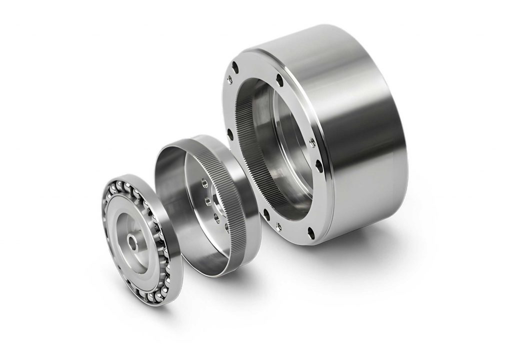
The core kinematic principle of a harmonic drive gear involves the pure rolling of the circular spline’s pitch circle on the deformed neutral curve of the flexspline. The wave generator, typically an elliptical cam, forces the thin-walled flexspline into a non-circular shape. To derive the mating tooth profile of the circular spline, one must precisely track the motion of each point on the flexspline tooth as it moves through the deformation field. Traditional approaches often introduce approximations at critical steps to simplify the complex integrals involved, particularly when calculating the tangential displacement of the neutral curve and the rotation of the tooth centerline relative to the radial vector. While computationally convenient, these approximations can lead to non-optimal conjugate tooth forms, resulting in uneven load distribution and residual backlash.
The proposed exact algorithm eliminates these approximations by a strategic choice of the independent variable. Instead of using the angular position \(\varphi\) of a point on the undeformed, circular flexspline neutral line, we adopt \(\varphi_1\) as the fundamental variable. Here, \(\varphi_1\) is the angular coordinate in a polar system centered on the wave generator’s axis, with the polar axis aligned with the generator’s major axis. This variable directly describes the position on the deformed elliptical neutral curve. The relationship between the deformed curve \(r(\varphi_1)\) and the wave generator’s geometry (an ellipse with semi-major axis \(a\) and semi-minor axis \(b\)) is given by:
$$ r(\varphi_1) = \frac{a}{\sqrt{1 + \epsilon^2 \sin^2 \varphi_1}} $$
where \(\epsilon = \sqrt{a^2/b^2 – 1}\) is the second eccentricity. The assumption of an inextensible neutral curve during deformation provides the crucial link between \(\varphi\) and \(\varphi_1\):
$$ r_m \varphi = \int_{0}^{\varphi_1} \sqrt{r(\xi)^2 + \left( \frac{dr(\xi)}{d\xi} \right)^2} d\xi = a \left[ E\left( e, \frac{\pi}{2} \right) – E\left( e, \arctan\left( \frac{\tan \varphi_1}{b/a} \right) \right) \right] $$
where \(r_m\) is the radius of the undeformed neutral curve, and \(E(k, \phi)\) is the incomplete elliptic integral of the second kind. This expression is exact and replaces the common approximate formula \(\varphi_1 \approx \varphi + v(\varphi)/r_m\), where \(v(\varphi)\) is the approximate tangential displacement.
Furthermore, the rotation \(\mu\) of the tooth centerline (the normal to the neutral curve) relative to the radial vector is computed exactly from the ellipse geometry:
$$ \mu(\varphi_1) = \arctan\left( \frac{-\dot{r}(\varphi_1)}{r(\varphi_1)} \right) = \arctan\left( \frac{\epsilon^2 \sin \varphi_1 \cos \varphi_1}{1 + \epsilon^2 \sin^2 \varphi_1} \right) $$
where \(\dot{r} = dr/d\varphi_1\). This avoids the approximation \(\mu \approx -\dot{\rho}/r_m\) often used when the radial deformation \(w\) is small relative to \(r_m\).
The kinematic transformation between the coordinate systems attached to the flexspline tooth (\(S_1\)) and the fixed circular spline (\(S_2\)) is central to the conjugate theory. Defining \(\beta = \gamma + \mu\) as the total orientation angle of the tooth in the fixed frame, and \(\gamma\) as the rotation of the flexspline’s non-deforming end, the homogeneous transformation matrix is:
$$ \mathbf{M}_{21} = \begin{bmatrix}
\cos \beta & \sin \beta & r \sin \gamma \\
-\sin \beta & \cos \beta & r \cos \gamma \\
0 & 0 & 1
\end{bmatrix} $$
The fundamental conjugate condition, derived from the requirement that the relative velocity at the contact point is orthogonal to the common normal, can be expressed as:
$$ \mathbf{n}_1^T \mathbf{\Phi} \dot{\mathbf{r}}_1 = 0 $$
where \(\mathbf{n}_1\) and \(\dot{\mathbf{r}}_1\) are the normal vector and velocity of a point on the flexspline tooth profile in \(S_1\), and the matrix \(\mathbf{\Phi}\) is:
$$ \mathbf{\Phi} = \begin{bmatrix}
0 & -r\dot{\beta} & -\dot{\gamma} \cos \mu \\
r\dot{\beta} & 0 & \dot{\gamma} \sin \mu \\
0 & 0 & 0
\end{bmatrix} $$
Critically, all derivatives (\(\dot{r}, \dot{\mu}, \dot{\gamma}, \dot{\beta}\)) are expressed explicitly as functions of \(\varphi_1\) using the exact elliptical relations and the kinematic roll-angle relation \(\dot{\gamma} = (z_g / z_r) \cdot (1 – \dot{r}/r_m) – 1\), where \(z_g\) and \(z_r\) are the tooth numbers of the circular spline and flexspline, respectively. This formulation contains no approximated or integrated terms, enabling a precise numerical solution.
The solution process is discretized. For each sample point \(\mathbf{r}_1^{(j)}\) on the flexspline tooth profile (e.g., a double-circular-arc profile defined by its geometric parameters), the conjugate equation is solved to find the specific wave generator angle \(\varphi_1^{(j)}\) at which that point is in contact. The corresponding conjugate point on the circular spline profile is then obtained via the exact transformation:
$$ \mathbf{r}_2^{(j)} = \mathbf{M}_{21}(\varphi_1^{(j)}) \cdot \mathbf{r}_1^{(j)} $$
The collection of all points \(\mathbf{r}_2^{(j)}\) defines the exact theoretical conjugate profile for the circular spline.
To demonstrate the practical significance, a harmonic drive gear with a double-circular-arc (DCA) tooth profile was analyzed. Key parameters are summarized in Table 1.
| Parameter | Symbol | Value |
|---|---|---|
| Module | \(m\) | 0.3175 mm |
| Radial Deformation Coefficient | \(w_0^*\) | 1.0 |
| Flexspline Teeth | \(z_r\) | 160 |
| Circular Spline Teeth | \(z_g\) | 162 |
| Major Semi-axis of Deformed Curve | \(a\) | \(r_m + w_0\) (where \(w_0 = m \cdot w_0^*\)) |
The conjugate existence domains for the flexspline tooth profile, calculated by both the exact and the traditional approximate algorithms, reveal critical differences. For the DCA profile, meshing typically occurs in two distinct angular intervals per tooth (Conjugate Zones I and II). The results are compared in Table 2.
| Algorithm | Conjugate Zone I (\(\varphi_1\)) | Conjugate Zone II (\(\varphi_1\)) | Total Conjugate Angular Range |
|---|---|---|---|
| Exact | [2.912°, 10.880°] | [12.494°, 46.969°] | ~42.46° |
| Approximate | [2.550°, 7.787°] | [13.652°, 46.018°] | ~37.41° |
The exact algorithm predicts a significantly larger total conjugate range (approximately 5° more). More importantly, the gap between Zone I and Zone II is smaller with the exact method. This implies a longer period of true conjugate (line) contact for each tooth pair during the meshing cycle, as opposed to potentially detrimental point contact at the transition, which enhances load-sharing and torsional stiffness.
The theoretical conjugate points for the circular spline were fitted to circular arcs for manufacturability. The resulting DCA profile parameters for the circular spline are compared in Table 3. The discrepancies, particularly in the convex arc radius \(\rho_a\), are non-negligible at the scale of precision gearing.
| Parameter | Exact Algorithm | Approximate Algorithm | Deviation |
|---|---|---|---|
| Concave Arc Radius, \(\rho_f\) | 0.6278 mm | 0.6170 mm | +1.75% |
| Convex Arc Radius, \(\rho_a\) | 0.5037 mm | 0.5505 mm | -8.51% |
| Convex Arc Center (x, y) | (0.6812, 25.7833) mm | (0.7252, 25.8010) mm | – |
The most direct measure of transmission precision is the backlash distribution. For the elliptical wave generator, approximately 23 tooth pairs are in simultaneous engagement on one side. The flank clearance (backlash) for each pair was calculated through simulated relative motion. The results, shown conceptually in Figure 1’s data, indicate that the harmonic drive gear designed with the exact algorithm exhibits a markedly more uniform and minimal backlash distribution. The backlash values for the exact design fluctuate within a very tight band around 0.2 µm, whereas the approximate design shows greater irregularity. Uniform backlash minimizes torque ripple and ensures smoother load transition between teeth.
A planar stress finite element analysis (FEA) was conducted to evaluate the mechanical performance. Two assemblies were modeled: one with the circular spline profile from the exact algorithm, and another from the approximate algorithm. After simulating the assembly of the elliptical wave generator and applying an input torque of 20 N·m to the circular spline (with the flexspline flange fixed), the von Mises stress distributions were compared. The key findings are summarized in Table 4.
| Performance Metric | Exact Algorithm Design | Approximate Algorithm Design |
|---|---|---|
| Maximum Stress in Flexspline | ~345 MPa | ~480 MPa |
| Stress Uniformity in Loaded Teeth (6 pairs) | More uniform (range: ~120 MPa) | Less uniform (range: >330 MPa) |
| Root Stress in Primary Loaded Teeth | Consistently lower by ~10 MPa | Higher and more variable |
| Risk of Tooth Tip Interference at Disengagement | Lower | Higher |
The FEA confirms the tangible benefits of the exact conjugate solution. The harmonic drive gear based on the exact profile not only operates at a lower peak stress but also distributes the load more evenly among the engaging tooth pairs. This leads to improved fatigue life, higher torque capacity, and reduced wear. The reduced risk of tooth tip interference also ensures smoother meshing throughout the rotation cycle.
In conclusion, the exact mathematical algorithm for solving conjugate profiles in harmonic drive gears, which meticulously avoids traditional approximations related to neutral curve elongation and tooth rotation, provides a superior foundation for design. By using the wave generator angle \(\varphi_1\) as the fundamental variable and employing exact elliptical relations and integrals, a more accurate kinematic model is achieved. The resulting conjugate tooth profile for the circular spline yields a larger and more continuous engagement zone, a significantly more uniform and near-zero backlash distribution, and a demonstrably better stress distribution under load. This methodology, while demonstrated for an elliptical wave generator, is fundamentally applicable to any wave generator contour defined by a known equation \(r(\varphi_1)\), making it a powerful general tool for optimizing high-performance, precision harmonic drive gear systems. The pursuit of such exact solutions is paramount for meeting the escalating demands for precision, reliability, and power density in advanced robotic and aerospace applications.