
The relentless drive towards automation and smart manufacturing has placed industrial robots at the forefront of technological advancement. The core of a robot’s dexterity and precision lies in its joints, which are almost invariably driven by high-performance speed reducers. Among these, the Rotary Vector (RV) reducer stands out as a paramount component for heavy-duty robotic applications due to its exceptional combination of high reduction ratio, compactness, superior torsional stiffness, high precision, and excellent overload capacity. The dynamic performance, positioning accuracy, and operational lifespan of an industrial robot are intrinsically linked to the behavior of its **RV reducer**. Within the complex kinematic chain of an **RV reducer**, the cycloidal gear plays a decisive role. Its interaction with the pin housing constitutes the critical second-stage reduction, directly governing the final output characteristics. Consequently, understanding the vibrational behavior, specifically the modal characteristics, of the cycloidal gear is fundamental to predicting and mitigating noise, vibration, and ensuring transmission stability for the entire **RV reducer** system.
Traditional modal analyses of components often simplify boundary conditions to free or idealized constraints. However, for the cycloidal gear within an operating **RV reducer**, such simplifications can lead to significant deviations from reality. The gear is simultaneously subjected to support from crankpin bearings and is in a state of multi-tooth meshing engagement with multiple needle rollers housed in the pin shell. This complex, combined constraint state drastically alters its dynamic signature compared to a free or simply supported condition. This article presents a comprehensive modal analysis of a cycloidal gear, progressively examining its vibrational characteristics under three distinct constraint scenarios: free state, bearing-supported state, and the realistic meshing state. The aim is to elucidate how the operational environment of an **RV reducer** fundamentally reshapes the dynamic identity of its core component, providing crucial insights for system-level dynamic design and optimization.
Kinematic Architecture and Operational Principles of the RV Reducer
The **RV reducer** is a sophisticated two-stage epicyclic gear system. Its primary components include the input sun gear, planetary gears, crankshafts (or planet carriers), cycloidal gears, needle rollers, a pin housing (needle shell), and the output flange (often integrated with the planet carrier of the second stage). The **RV reducer** achieves its high reduction ratio through a serial combination of a first-stage involute planetary train and a second-stage cycloidal planetary train.
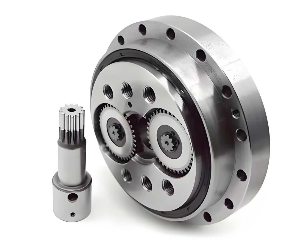
The power flow in a typical fixed-pin-housing configuration is as follows: High-speed rotation from a servo motor is input to the sun gear. This gear meshes with two or three planetary gears, constituting the first-stage reduction. The planetary gears are mounted on crankshafts, causing these shafts to rotate. Each crankshaft carries an eccentric portion on which a cycloidal gear is mounted via a roller bearing. The rotation of the crankshaft imparts an eccentric motion to the cycloidal gear. However, because the cycloidal gear is also meshing with the stationary needle rollers fixed in the pin housing, its eccentric rotation is constrained, forcing it to undergo a slow, reverse planetary rotation relative to the crankshaft’s direction. This interaction between the cycloidal gear’s lobes and the needle rollers constitutes the second, and primary, reduction stage. The final low-speed, high-torque output is taken from the output flange, which is connected to the cycloidal gears through a set of pin holes and output pins. The total reduction ratio \( i_{total} \) of the **RV reducer** can be expressed as:
$$ i_{total} = (1 + \frac{Z_p}{Z_s}) \times (-\frac{Z_p}{Z_c – Z_p}) $$
where \( Z_s \) is the number of teeth on the sun gear, \( Z_p \) is the number of teeth on the planetary gear, and \( Z_c \) is the number of teeth on the cycloidal gear. The negative sign indicates a direction reversal. The second term, representing the cycloidal stage, provides the majority of the speed reduction.
Theoretical Foundations for Modal and Meshing Analysis
Modal Analysis Theory
Modal analysis is the study of the inherent vibration characteristics of a structure. It determines the natural frequencies, damping factors, and mode shapes—the patterns of deformation—at those frequencies. For a linear, undamped multi-degree-of-freedom system, the equation of motion is:
$$ \mathbf{M}\{\ddot{x}\} + \mathbf{K}\{x\} = \{0\} $$
where \( \mathbf{M} \) is the mass matrix, \( \mathbf{K} \) is the stiffness matrix, \( \{x\} \) is the displacement vector, and \( \{\ddot{x}\} \) is the acceleration vector. Assuming harmonic motion \( \{x\} = \{\phi\} e^{j\omega t} \), this leads to the fundamental eigenvalue problem:
$$ (\mathbf{K} – \omega^2 \mathbf{M}) \{\phi\} = \{0\} $$
The solutions are eigenvalues \( \omega_i^2 \) (where \( \omega_i \) is the i-th natural frequency in rad/s) and corresponding eigenvectors \( \{\phi\}_i \) (the i-th mode shape). The natural frequency in Hertz is \( f_i = \omega_i / 2\pi \). The stiffness matrix \( \mathbf{K} \) is directly influenced by the applied constraints; altering boundary conditions changes \( \mathbf{K} \), thereby shifting all natural frequencies and mode shapes. This principle is central to comparing the free, bearing-supported, and meshing states of the cycloidal gear in an **RV reducer**.
Geometry and Meshing of the Cycloidal Profile
The tooth profile of the cycloidal gear is a shortened epicycloid, generated by a rolling circle of radius \( r_r \) on a base circle of radius \( R_p \) (the pitch circle radius of the needle roller distribution). The parametric equations defining the ideal tooth profile are:
$$ x = (R_p – r_r)\sin\theta – (R_p – r_r)\frac{\sin(Z_p\theta)}{Z_p} – e\sin((1-Z_p)\theta) $$
$$ y = (R_p – r_r)\cos\theta – (R_p – r)\frac{\cos(Z_p\theta)}{Z_p} + e\cos((1-Z_p)\theta) $$
where \( e \) is the eccentricity of the crankshaft, \( Z_p \) is the number of needle rollers (equivalent to the generating pinion teeth), and \( \theta \) is the rolling angle. In practice, to ensure proper backlash and lubrication, the needle roller is not a point but has a radius \( r_{rp} \). The working profile of the cycloidal gear is therefore the equidistant curve offset inward from the theoretical profile by this roller radius. The instantaneous meshing force between a cycloidal tooth and a needle roller is highly dependent on the load distribution and the position-dependent meshing stiffness \( k_m(\theta) \). This stiffness, when the gear is engaged with multiple teeth, contributes significantly to the overall structural stiffness matrix \( \mathbf{K}_{mesh} \) in the meshing state analysis. An approximate expression for the comprehensive meshing stiffness considering tooth bending, shear, and Hertzian contact for a single tooth pair is complex, but its effect is to add a position-variant stiffness coupling between the cycloidal gear and the pin housing at each engagement point.
Finite Element Modeling and Constraint Definitions
To perform a comparative modal analysis, a high-fidelity 3D model of a cycloidal gear from an **RV reducer** (akin to model RV-40E) was created. The gear material is GCr15 bearing steel. Its key properties are summarized in the table below:
| Component | Material | Density, ρ (kg/m³) | Young’s Modulus, E (GPa) | Poisson’s Ratio, ν |
|---|---|---|---|---|
| Cycloidal Gear | GCr15 | 7810 | 208 | 0.30 |
| Needle Roller | GCr15 | 7810 | 208 | 0.30 |
| Pin Housing | QT450 | 7000 | 173 | 0.30 |
The finite element model was constructed and solved using a commercial FE package. A free-mesh strategy with a refined element size of 2.5 mm was used for the cycloidal gear, resulting in a model with approximately 77,740 nodes and 49,157 solid elements. This ensured a balance between computational efficiency and accuracy for capturing the complex geometry and mode shapes.
Defining the Three Constraint States
Three distinct FE models were developed to represent the different operational conditions of the cycloidal gear within the **RV reducer**.
State 1: Free State. This is the baseline condition. The cycloidal gear model has no constraints applied whatsoever. It represents the gear’s inherent dynamic properties in a vacuum, devoid of any external influence. The stiffness matrix \( \mathbf{K}_{free} \) is singular due to the presence of six rigid body modes (three translational and three rotational) at 0 Hz, which are typically excluded from the analysis of elastic modes.
State 2: Bearing-Supported State. This model introduces the primary support condition. Cylindrical support constraints (simulating roller bearings) are applied to the inner surfaces of the two crankpin bearing bores on the cycloidal gear. These constraints allow radial stiffness but restrict displacement in the radial direction of the bore, approximating the support provided by the bearings on the eccentric portions of the crankshafts. This state increases the system’s stiffness, leading to higher natural frequencies compared to the free state, and eliminates rigid body modes. The stiffness matrix becomes \( \mathbf{K}_{bearing} \), where \( \mathbf{K}_{bearing} > \mathbf{K}_{free} \) in a positive-definite sense.
State 3: Meshing State. This is the most comprehensive and realistic model, aiming to simulate the actual working condition of the cycloidal gear inside an assembled **RV reducer**. A sub-assembly model is created, consisting of the cycloidal gear, multiple needle rollers, and the pin housing. The pin housing is fixed at its mounting bolt holes, simulating its attachment to the robot arm. The cycloidal gear is constrained with the same bearing supports in its bores as in State 2. Crucially, “Bonded” or frictional contact conditions are defined between the tooth flanks of the cycloidal gear and the cylindrical surfaces of the needle rollers. This contact formulation effectively couples the degrees of freedom at the meshing interfaces, introducing a distributed, multi-point stiffness connection \( \mathbf{K}_{contact} \) between the gear and the grounded housing. The overall system stiffness matrix in this state is a superposition: \( \mathbf{K}_{meshing} = \mathbf{K}_{bearing} + \mathbf{K}_{contact} \). The mesh for this assembly was refined, with the pin housing meshed at 3 mm, resulting in a combined model of over 230,000 nodes. This state most accurately represents the operational dynamics of the **RV reducer**’s cycloidal stage.
Results, Comparative Analysis, and Discussion
The first ten elastic natural frequencies and their associated mode shapes were extracted for the cycloidal gear under each of the three constraint states. The results reveal a profound and systematic evolution of dynamic behavior.
Frequency Evolution Across Constraint States
The tabulated data and the comparative plot clearly demonstrate the stiffening effect of progressively realistic constraints in an **RV reducer**.
| Mode Order | Free State | Bearing-Supported State | Meshing State |
|---|---|---|---|
| 1 | 2157.8 | 2757.7 | 3114.7 |
| 2 | 2279.1 | 2799.9 | 3120.8 |
| 3 | 3480.5 | 4807.7 | 4921.2 |
| 4 | 5341.2 | 5293.7 | 5983.5 |
| 5 | 5429.5 | 6175.7 | 7307.5 |
| 6 | 6593.4 | 7373.5 | 8221.4 |
| 7 | 6944.0 | 8533.4 | 9318.6 |
| 8 | 7826.2 | 9056.9 | 10170.0 |
| 9 | 9480.0 | 10233.0 | 10591.0 |
| 10 | 9694.8 | 10272.0 | 11832.0 |
The transition from Free to Bearing-Supported state causes a significant first jump in frequencies. For instance, the first natural frequency increases by approximately 28%. This is expected, as the bearing constraints eliminate free motion and add substantial radial stiffness at the gear’s core. The transition from Bearing-Supported to Meshing state induces a further, and often more dramatic, increase. The first mode frequency rises another 13%, and for some higher modes (e.g., Mode 5), the increase exceeds 18%. This second jump is directly attributable to the distributed stiffness provided by the simultaneous meshing engagement with multiple needle rollers. The gear is no longer a cantilever-like structure supported only at its center; it is now also anchored at its periphery through the teeth. This transforms its boundary condition from a centrally-supported disc to a peripherally-constrained ring-plate hybrid structure, with a consequent substantial boost in overall rigidity. The relationship can be conceptually summarized as:
$$ f_{i,\text{meshing}} > f_{i,\text{bearing}} > f_{i,\text{free}} \quad \text{for all elastic modes } i $$
This hierarchy is visually evident in the frequency spectrum plot, where the meshing state curve lies consistently above the others.
Transformation of Mode Shapes
The influence of constraints extends beyond mere frequency shifts; it fundamentally reshapes the deformation patterns of the cycloidal gear. In the Free State, low-order modes are dominated by gross, beam-like bending and torsional deformations of the entire gear body. For example, the first mode might be a bending along the gear axis, and the second a twisting about it.
In the Bearing-Supported State, the central bearing bores become nodal regions—points of minimal displacement. The mode shapes localize more, involving distortions of the gear body between the bores and the outer rim. Bending modes are altered, and new types of in-plane (X-Y plane) oscillatory or torsional modes of the rim itself become prominent at lower orders.
The Meshing State introduces the most radical change. The engagement with the needle rollers effectively “pins” the cycloidal gear at discrete points around its circumference. This severely restricts deformation in the radial and tangential directions at the tooth engagement zones. As a result:
- Localized Deformation: Mode shapes tend to show more localized deformation in the sectors between engaged tooth zones, rather than global gear body deformation.
- Shift to Higher-Order Deformation Patterns: What was a simple bending mode in the free state may transform into a complex, multi-lobed (nodal diameter) deformation pattern of the gear rim in the meshing state. The system must now excite higher-strain-energy deformation patterns to overcome the peripheral constraint.
- Altered Nodal Lines: The lines of zero displacement (nodal lines) no longer pass through the geometric center freely but are dictated by the pattern of meshing constraints. For instance, a mode that appeared as a simple two-node diameter bending might, under meshing, become a four- or six-node diameter pattern.
This evolution confirms that analyzing the cycloidal gear in isolation (free or simply supported) yields mode shapes that are not representative of its actual vibrational behavior within a functioning **RV reducer**. The true operational modes are those calculated under the meshing state constraints.
Implications for RV Reducer Design and Dynamic Analysis
The findings have several critical implications for the engineering of high-performance **RV reducers**:
1. Resonance Avoidance: The excitation sources in an **RV reducer** are manifold: gear mesh frequencies from both the involute and cycloidal stages, eccentric mass forces from the crankshafts, and harmonics from the driving motor. The operational excitation spectrum must be compared against the meshing-state natural frequencies of the cycloidal gear, not its free-state frequencies. Designing based on free-state frequencies would be dangerously non-conservative, as the actual system is much stiffer and has higher resonant frequencies. A significant margin must be maintained between excitation frequencies (e.g., the cycloidal tooth pass frequency \( f_{mesh} = n \times f_{output} \), where \( n \) is the number of needle rollers) and the fundamental meshing-state natural frequencies of critical components to avoid resonance-induced noise, vibration, and accelerated fatigue.
2. Dynamic Transmission Error: Transmission error (TE), a prime source of vibration and noise in geared systems, is influenced by the dynamic response of the components. The dynamic mesh stiffness variation is modulated by the system’s modal properties. The significantly higher and differently shaped modal stiffness of the cycloidal gear in the meshing state will alter its dynamic compliance under load, thereby affecting the overall dynamic TE of the **RV reducer**. Accurate system-level dynamic models must incorporate the meshing-state constrained modal properties of the cycloidal gear.
3. Structural Optimization: If structural optimization of the cycloidal gear (e.g., lightweighting, shape optimization) is undertaken to improve performance, the objective function and constraints must be evaluated under the meshing-state condition. Optimizing for free-state frequency maximization could lead to a design that performs sub-optimally or even has lower frequencies when placed in the actual constrained environment of the **RV reducer**. The finite element model with meshing constraints should serve as the basis for any such optimization loop.
4. Fault Diagnosis: In condition monitoring and fault diagnosis of **RV reducers**, changes in vibration spectra are key indicators. Understanding the normal modal behavior under meshing conditions provides a baseline. Damage such as a cracked tooth, a worn bearing bore, or a missing needle roller would locally alter the constraint stiffness matrix \( \mathbf{K}_{contact} \) or \( \mathbf{K}_{bearing} \), leading to detectable shifts in the meshing-state natural frequencies and mode shapes. This offers a potential pathway for model-based diagnostics.
Conclusion and Future Perspectives
This detailed modal investigation underscores a fundamental principle in the dynamics of precision mechanical systems: the boundary condition is not a secondary detail but a primary determinant of dynamic behavior. For the cycloidal gear, a pivotal component within an **RV reducer**, the shift from a free or simply supported state to its operational meshing state induces a profound metamorphosis. Natural frequencies experience a two-stage elevation—first from bearing support and second, more significantly, from multi-tooth engagement with the pin housing. Concurrently, the fundamental patterns of vibration (mode shapes) are radically transformed from global body motions to localized, constrained rim deformations.
Therefore, any credible analysis targeting the dynamic performance, noise-vibration-harshness (NVH) characteristics, or structural integrity of an **RV reducer** must account for this realistic meshing-state condition. The results presented provide a validated framework and quantitative data that can feed into system-level multi-body dynamic simulations, finite element analysis of assembled reducers, and targeted design optimization processes. Future work should focus on extending this analysis to include the effects of preload from the crankshaft bearings, the nonlinearity of Hertzian contact stiffness in the mesh, and the coupling between the two cycloidal gears in a standard **RV reducer** configuration. Furthermore, experimental modal analysis on a fully assembled **RV reducer** under simulated load would be invaluable for correlating and refining these computational models, paving the way for the next generation of ultra-quiet, high-precision, and dynamically stable robotic drive systems.