
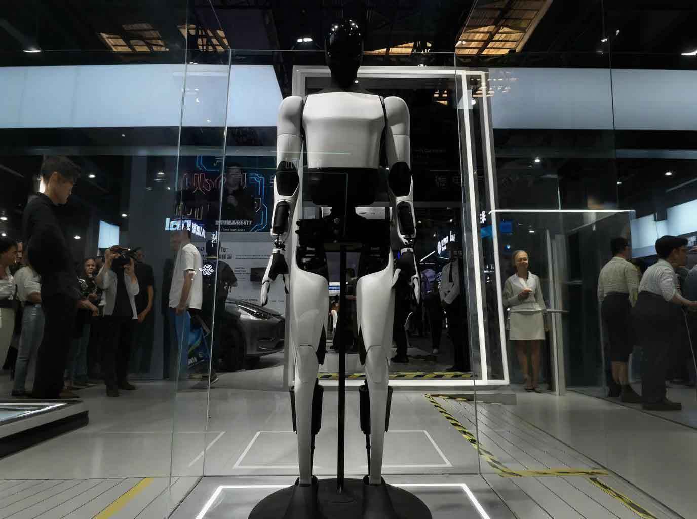
In the past few decades, the field of humanoid robotics has evolved from a distant science-fiction dream into a tangible engineering discipline. The development of an embodied robot that can walk, perceive, and interact with the real world requires deep integration of mechanical design, embedded systems, real-time control, and intelligent algorithms. This thesis focuses on the design of a humanoid robot controller and the study of gait control algorithms for such an embodied robot. The entire system is built upon a hierarchical master-slave architecture, where high-level decisions are made on an industrial PC and low-level joint actuation is managed by a dedicated motion control board. The research covers hardware selection, circuit design, steering gear control, kinematics modelling, and gait planning. Special emphasis is placed on the ZMP (Zero Moment Point) stability criterion and the 3D linear inverted pendulum model. In addition, an action-frame-based gait generation method is proposed and experimentally validated, demonstrating the practical feasibility of the designed embodied robot.
1. Introduction and Research Background
The emergence of industrial robots in the mid-20th century marked the beginning of automated manufacturing. However, the dream of creating an embodied robot that resembles the human body and moves like a human has been pursued only since the 1960s. Unlike conventional industrial robots fixed to a base, a humanoid robot must maintain dynamic balance while walking on two legs. This requires a high number of degrees of freedom (DoF), typically more than twenty, and a sophisticated control system that can coordinate multiple joints in real time. The embodied robot described in this thesis is designed to mimic the human skeletal structure and to operate in environments built for humans. The key challenges are the nonlinearities, strong coupling, and the need for real-time stability.
Research on humanoid robots has progressed rapidly in the United States, Japan, Germany, and other developed countries. Iconic platforms such as ASIMO from Honda, ATLAS from Boston Dynamics, and iCub from the Italian Institute of Technology have demonstrated advanced walking, manipulation, and even social interaction. In China, the development started later but has accelerated, with robots like the “Forerunner” from National University of Defense Technology and the BHR series from Beijing Institute of Technology. The recent TALOS robot from the Shenzhen company UBTECH has shown that domestic humanoid robots can reach a world-class level. Nevertheless, many technical gaps remain, especially in low-cost, compact, and reliable gait control for small to medium sized embodied robot platforms.
2. Gait Planning and Research Status
The gait planning problem for an embodied robot is central to its ability to perform tasks in human environments. The existing methods can be divided into three categories: bio-inspired, intelligent learning, and model-based approaches. Bio-inspired methods often use human motion capture data to generate joint trajectories. Intelligent learning methods employ neural networks, fuzzy logic, or genetic algorithms to adapt the gait to uncertain terrains. Model-based methods, such as the D-H kinematic model, the 3D linear inverted pendulum, and the cart-table model, provide analytical frameworks for generating stable locomotion. In this work, both the 3D linear inverted pendulum and the action-frame method are investigated and compared.
| Method | Key Idea | Advantages | Disadvantages |
|---|---|---|---|
| Bio-inspired | Human motion capture data | Natural appearance | Robot-specific structure mismatch |
| Intelligent learning | Neural networks, genetic algorithms | Adaptive, fault tolerant | Requires training, not always predictable |
| Model-based D-H | Coordinate transformation | Explicit kinematic relationships | Does not handle balance directly |
| 3D Linear Inverted Pendulum | Simplify mass to a single point | Well-suited for dynamic walking | Requires offline ZMP planning |
| Cart-table model | Mass on a moving cart over a table | Direct ZMP generation | Model simplicity limits terrain adaptation |
3. Controller Design for the Embodied Robot
The overall architecture of my embodied robot adopts a master-slave control configuration. The master controller, a PICO-HC101 industrial motherboard, is responsible for high-level tasks such as image processing, path planning, and gait algorithm computation. The slave controller, based on an STM32F103RET6 microcontroller, handles low-level real-time tasks such as servo actuation and sensor data acquisition. This separation allows the system to be modular and easier to debug.
3.1 Main Controller Selection
The PICO-HC101 motherboard uses an Intel Atom E3845 processor with dual-core capability and low power consumption. It has a compact size of 56.5 mm × 66 mm, which is ideal for the space-constrained body of a small humanoid robot. The board supports multiple USB interfaces, serial ports, and audio outputs, which are necessary for connecting the camera, the motion control board, and the speaker. The operating system chosen for the master controller is Ubuntu 12.04, due to its open-source nature, low resource usage, and excellent support for C/C++.
| Feature | Value |
|---|---|
| Processor | Intel Atom E3845 / Celeron J1900 |
| Dimensions | 56.5 mm × 66 mm |
| RAM | 64 GB SSD |
| USB | USB 3.0 × 1, USB 2.0 × 2 |
| Serial Ports | RS-232 × 1, RS-232/422/485 × 1 |
| Audio | Line-out |
| Operating System | Ubuntu 12.04 |
3.2 Motion Control Board Hardware Design
The motion control board is designed to interface between the master controller and the servo motors. It must be highly reliable because all joint commands pass through it. The core of the board is an STM32F103RET6 microcontroller running at 72 MHz with 256 KB of flash memory. The board includes a crystal oscillator circuit, a reset circuit, power conversion circuits, communication circuits, and sensor circuits.
3.2.1 Crystal Oscillator and Reset Circuit
The STM32 requires an external 8 MHz crystal oscillator to provide the system clock. Two 20 pF load capacitors are placed close to the oscillator pins to ensure stability. The reset circuit uses an external capacitor and a push button. When the power is turned on, the capacitor charges and the reset pin remains low until the voltage reaches a safe threshold, providing a reliable power-on reset.
3.2.2 Power Supply Circuit
Different parts of the system require different voltage levels. The STM32 and sensors operate at 3.3 V, the TTL communication uses 5 V, and the servos require 11.1 V from a lithium battery. The battery is a 11.1 V / 1800 mAh lithium polymer pack. The power circuit first uses an LM78M05 linear regulator to step down the battery voltage to 5 V. Then an EZ1117 low-dropout regulator converts 5 V to 3.3 V. A LED indicator is added to verify the 3.3 V output.
| Module | Voltage (V) | Regulator |
|---|---|---|
| MCU | 3.3 | EZ1117 |
| Sensor | 3.3 | EZ1117 |
| Servo | 11.8 (battery) | Direct |
| TTL communication | 5 | LM78M05 |
| Main controller | 12 (from separate supply) | External |
3.2.3 Communication Circuits
The communication between the master controller and the motion control board is implemented via a USB-to-serial converter. I selected the FT232 chip because of its stability and good driver support. The FT232 converts USB data to UART signals and vice versa. Meanwhile, the communication between the motion control board and the MX-28T servos uses TTL-level half-duplex UART. To support future upgrades, I also included an RS-485 transceiver (MAX3440) on the board. The circuit uses a 74HC126 buffer to switch between transmit and receive modes.
3.2.4 Sensor Circuits
To maintain balance, the embodied robot uses two inertial sensors: an LIS331DLH triple-axis accelerometer and an L3G4200D triple-axis gyroscope. These sensors are mounted at the geometric center of the robot to obtain accurate attitude data. The LIS331DLH provides a 16-bit digital output over I2C or SPI. The L3G4200D measures angular velocity up to ±500 dps. The relationship between the raw sensor values and the physical quantities is linear, which simplifies calibration. I designed the sensor circuits with decoupling capacitors and connected the interrupt lines to the STM32 for real-time data processing.
| Sensor | Measured Quantity | Range | Interface |
|---|---|---|---|
| LIS331DLH | Linear acceleration | ±4 g | I2C/SPI |
| L3G4200D | Angular velocity | ±500 dps | I2C/SPI |
3.3 Actuator and Peripheral Design
The robot is driven by DYNAMIXEL MX-28T digital servos. Each servo contains a DC motor, a gear train, and an embedded 32-bit ARM controller. The MX-28T supports a 12-bit absolute encoder, giving a resolution of 0.088 degrees. It communicates through a half-duplex asynchronous serial bus at up to 4.5 Mbps. I selected the TTL version because it simplifies wiring. The servos provide current position, speed, load, temperature, and voltage feedback, which is essential for safe operation.
For perception, I selected a Logitech C905 web camera. It features a Carl Zeiss lens, auto-focus, 2-megapixel sensor, and supports 1080p resolution. The camera is used for ball tracking and obstacle recognition. The speaker circuit uses an LM386 audio amplifier to provide voice feedback. A microphone circuit based on an LM324 operational amplifier is also included for future human-robot interaction. The final PCB was a four-layer design to reduce noise and improve signal integrity.
3.4 Software Development Platform
The software framework of the embodied robot is divided into three layers: the master control module, the motion control module, and the execution module. The master controller runs Ubuntu Linux and communicates with the motion control board through a serial port. The motion control board runs bare-metal C code developed in Keil MDK. Commands are sent in the form of data packets that specify the target position, speed, and torque for each servo. The master controller can also request sensor data at a frequency of 50 Hz. This modular software structure simplifies the implementation of complex behaviors.
4. Steering Gear Control Design
4.1 Servo Selection and Specifications
The MX-28T servo was chosen after comparing it with DC motors and stepper motors. DC motors have low position accuracy and require additional gearboxes, while stepper motors are heavy and require separate drivers. The MX-28T integrates the driver and controller into a single module, making it ideal for a compact embodied robot. Its specifications are summarized in the table below.
| Parameter | Value |
|---|---|
| MCU | STM32F103C8 @ 72 MHz |
| Position Sensor | Contactless absolute encoder (12-bit, 360°) |
| Motor | Maxon |
| Communication Speed | 8000 bps ~ 4.5 Mbps |
| Stall Torque (at 12V) | 2.5 N·m |
| No-load Speed (at 12V) | 55 rpm |
| Minimum Control Angle | 0.088° |
| Operating Voltage | 10 ~ 14.8 V |
| Communication Mode | Half-duplex asynchronous serial |
4.2 Communication and Instruction Design
The servos are connected in a daisy-chain bus configuration. Each servo has a unique ID.The master controller sends an instruction packet that starts with two bytes of 0xFF, followed by the slave ID, packet length, instruction, parameters, and a checksum. The checksum is calculated as the bitwise NOT of the sum of all bytes except the start bytes. The response from a servo is a status packet containing its current position, load, temperature, and other data. The table below defines the memory control table of the MX-28T.
| Address | Name | Function | Access |
|---|---|---|---|
| 0x18 | Torque ON/OFF | Enable or disable motor torque | RW |
| 0x1E | Goal Position (L/H) | Target joint angle (0-4095) | RW |
| 0x20 | Moving Speed (L/H) | Target angular velocity | RW |
| 0x22 | Torque Limit (L/H) | Maximum output torque | RW |
| 0x24 | Present Position | Current position | R |
| 0x26 | Present Speed | Current velocity | R |
| 0x2A | Present Voltage | Input voltage | R |
| 0x2B | Present Temperature | Internal temperature | R |
For the embodied robot with 20 servos, sending individual commands to each servo would cause a significant delay (about 264 ms). To overcome this, I used the SYNC WRITE function of the MX-28T protocol. This function allows multiple servos to receive their target positions in a single packet. The servos do not act immediately; instead, they execute the command only after receiving an ACTION instruction, thereby achieving synchronized motion.
4.3 Servo ID Allocation and Softness Design
I assigned servo IDs in a symmetric manner to simplify programming. The IDs are mirrored between the left and right sides of the body. For example, the left hip joint and right hip joint have consecutive IDs. The complete ID assignment is not listed in the thesis to avoid unnecessary confusion, but it follows the anatomical order from legs to arms.
Softness control improves the impact resistance during walking. It is achieved by setting the compliance margin and compliance slope parameters. I constructed a test bench and measured the response time of a servo under different compliance margin values. The results showed that as the margin increased, the response time increased. Therefore, I set the compliance margin to 0 for precise movement. For the compliance slope, I found the optimal value to be 52, where the response time was minimal. Similar procedures were applied to all servos.
4.4 Servo Debugging and Testing
Before gait implementation, I built a graphical interface to detect all servos. If a servo was healthy, the interface displayed “OK”; otherwise, it showed “NO”. After successful detection, I tested the right arm joints (IDs 1, 3, 5). By moving the arm manually, the master controller recorded the position values. I sampled the data at 50 ms intervals and plotted the trajectories. The plots confirmed that the servos responded smoothly and the feedback was accurate, providing a reliable basis for further experiments.
5. Gait Planning and Control Algorithms
5.1 Kinematics Analysis of the Embodied Robot
Kinematics describes the relationship between joint angles and the position/orientation of the robot links. I used the Denavit-Hartenberg (D-H) convention to establish coordinate frames on each joint. The positive kinematic model was derived by multiplying the homogeneous transformation matrices along the kinematic chain. For the lower body, the base coordinate frame is placed at the ankle joint of the supporting foot. The transformation from the world frame to a point on the link can be expressed as:
$$ T_i^0 = B_1 B_2 \cdots B_i $$
where \(B_k\) is the D-H transformation matrix for joint \(k\). For a planar rotation about the z-axis, the general form is:
$$
B_k = \begin{bmatrix}
\cos\theta_k & -\sin\theta_k & 0 & a_{k-1} \\
\sin\theta_k & \cos\theta_k & 0 & d_{k-1} \\
0 & 0 & 1 & 0 \\
0 & 0 & 0 & 1
\end{bmatrix}
$$
After computing the forward kinematics for all limbs, I obtained the position of the center of mass (CoM) and the feet. The inverse kinematics is needed to determine joint angles from a desired foot position. Since closed-form solutions are complex for a high-DoF robot, I used a numerical method based on the Jacobian. The iterative algorithm updates the joint vector \(\mathbf{q}\) to minimize the error between the current end-effector pose and the desired pose.
5.2 Zero Moment Point (ZMP) Stability Criterion
The Zero Moment Point (ZMP) is the point on the ground where the horizontal component of the moment of all inertial and gravitational forces is zero. If the ZMP lies inside the convex hull of the support foot, the robot is dynamically stable. The ZMP coordinates can be computed from the robot’s mass distribution and acceleration:
$$
\begin{aligned}
X_{\text{ZMP}} &= \frac{\sum_{i=1}^n m_i (\ddot{Z}_i + g) X_i – \sum_i m_i \ddot{X}_i Z_i – \sum_i [I_{iy} \ddot{\Omega}_{ix}]}{\sum_{i=1}^n m_i (\ddot{Z}_i + g)} \\
Y_{\text{ZMP}} &= \frac{\sum_{i=1}^n m_i (\ddot{Z}_i + g) Y_i – \sum_i m_i \ddot{Y}_i Z_i – \sum_i [I_{ix} \ddot{\Omega}_{iy}]}{\sum_{i=1}^n m_i (\ddot{Z}_i + g)}
\end{aligned}
$$
In the above formulas, \(m_i\) is the mass of the \(i\)-th link, \((X_i, Y_i, Z_i)\) is its center of mass position, \(\ddot{X}_i, \ddot{Y}_i, \ddot{Z}_i\) are its accelerations, \(I_{ix}\) and \(I_{iy}\) are the moments of inertia, and \(\Omega_{ix}, \Omega_{iy}\) are the angular accelerations.
5.3 3D Linear Inverted Pendulum Model
The 3D linear inverted pendulum (3D-LIP) is an elegant model for humanoid walking. The entire mass of the robot is assumed to be concentrated at the CoM, and the supporting leg is represent by a massless telescopic link. The foot contact is considered as a point, such that there is no moment at the contact point. The motion of the CoM is governed by:
$$
\begin{cases}
M \ddot{x} = f_x = f \frac{x}{l} \\
M \ddot{y} = f_y = f \frac{y}{l} \\
M \ddot{z} = f_z – M g = f \frac{z}{l} – M g
\end{cases}
$$
By imposing a constraint plane \(z = k_x x + k_y y + z_c\), one can cancel the coupling and obtain the famous linear equations:
$$
\ddot{x} = \frac{g}{z_c} x, \qquad \ddot{y} = \frac{g}{z_c} y
$$
This model allows the CoM trajectory to be planned independently of the leg configuration, provided that the foot placement is chosen correctly. I simulated the gait using MATLAB. The figures (not shown here) depicted the CoM trajectories in the X and Z directions during the stepping phase. For my embodied robot, I first generated a reference ZMP trajectory and then computed the corresponding CoM motion using the 3D-LIP equations. The gait was parameterized by step length, step height, and walking period.
5.4 Action Frame-Based Gait Generation
Although the 3D-LIP provides a solid theoretical foundation, implementing it directly on a low-cost microcontroller with 20 servos is challenging. Therefore, I developed a simpler and more practical method based on action frames. The idea is similar to animation: the walking cycle is divided into a series of key frames, and each frame specifies the desired angle of every joint. The frames are stored in the master controller’s memory and then played back sequentially with a defined time interval. The joint angles for each frame were initially computed using inverse kinematics and later fine-tuned experimentally.
| Frame | Description | Hip Pitch | Knee Pitch | Ankle Pitch |
|---|---|---|---|---|
| 1 | Initial standing | 0° | 0° | 0° |
| 2 | Crouching | −10° | 20° | −10° |
| 3 | Shift weight right | 5° | −5° | 0° |
| 4 | Left foot lifted | −20° | 40° | −10° |
| 5 | Left foot placed | 0° | 0° | 0° |
I implemented the action frame generator in the Linux environment. The user interface displayed the current position of all servos. After manually moving the robot limbs (with torque off) to a desired pose, the new positions were saved into a page of the memory. Each page could contain up to 7 steps. A “Link to Next” feature allowed pages to be chained for longer actions. The playback time was set to 1 second per step by default. After several iterations, I achieved a stable walking cycle. The gait was then transferred to the embodied robot and verified through experiments.
5.5 Comparison of Gait Planning Algorithms
Both the 3D-LIP and the action-frame method were tested. The 3D-LIP method is systematic and suitable for more complex walking patterns, but it requires significant computational resources and careful ZMP compensation. On the other hand, the action-frame method is straightforward and easy to implement on the current hardware. However, it does not guarantee dynamic balance unless the frames are manually tuned. Table below summarizes the comparison.
| Criteria | 3D Linear Inverted Pendulum | Action Frame |
|---|---|---|
| Computational cost | High | Low |
| Stability guarantee | Yes (via ZMP) | No (needs heuristic tuning) |
| Adaptability | Good for varying step sizes | Limited to pre-defined frames |
| Implementation effort | High | Low |
| Suitability for my robot | Future optimization | Currently used |
6. Experimental Results and Analysis
6.1 Prototype and Gait Implementation
The complete embodied robot prototype is shown in the figure below (not included due to the absence of an image). The robot has 20 DoF and stands about 50 cm tall. This height was chosen as a trade-off between torque and stability. During the experiments, the action-frame playback successfully made the robot take multiple steps. The sequence of walking is illustrated by four snapshots: (a) initial crouching, (b) shifting weight to the left leg, (c) lifting the right foot, and (d) placing the right foot forward. The left and right leg movements were symmetric by swapping the servo parameters. The actual walking speed was about 5 cm per step with a 1 second step period.
6.2 Gyroscope and Accelerometer Calibration
To evaluate the sensor feedback, I performed a calibration experiment. The embodied robot was placed in an upright standing pose, then it was forced to fall forward, and finally it was lifted back to standing. The gyroscope and accelerometer data were recorded at a sampling rate of 50 Hz. The raw data were imported into MATLAB and plotted. The gyroscope Y-axis showed a significant spike during the forward fall, while the X-axis data had a smaller fluctuation due to slight lateral sway. The accelerometer data showed a large change in the Y-axis (forward direction) and only a small change in the X-axis. These responses matched the expected physical behavior, confirming that the sensors were correctly calibrated and capable of providing feedback for balance control.
7. Conclusion and Future Work
In this thesis, I have presented a complete design for a humanoid robot controller and its gait control algorithm. The embodied robot employs a master-slave architecture with an industrial PC and an STM32-based motion control board. The hardware design covered power supply, communication, sensor, and actuator circuits. The MX-28T servos were successfully integrated and controlled through a bus protocol. I established the kinematic model of the robot and derived the ZMP stability criterion. A MATLAB simulation of the 3D linear inverted pendulum confirmed the validity of the dynamic model. The action-frame gait generation method proved to be practical for achieving bipedal walking on the actual hardware.
Several aspects remain for future improvement. First, the motion control board can be redesigned to reduce sensor damage by improving the PCB layout and adding protective circuits. Second, the MX-28T servos limit the height and payload of the robot; a robot with more powerful actuators would allow taller structures. Third, the 3D-LIP algorithm needs to be ported to the onboard Linux system to enable dynamic walking on uneven terrain. The action-frame method can also be optimized by interpolating joint angles to smooth the transitions between frames. The ultimate goal is to create a truly embodied robot that can autonomously navigate and interact with the physical world. Despite the challenges, the development of this prototype provides a foundation for future research in humanoid robotics.
In conclusion, the design and implementation described here demonstrate that a low-cost, compact embodied robot is capable of human-like walking through a carefully tailored control architecture and a well-defined gait planning methodology. The knowledge gained from this work can be extended to other robotic systems and contributes to the broader field of embodied artificial intelligence.