
In the field of precision robotics and industrial automation, the RV reducer, or Rotate Vector reducer, plays a critical role due to its compact design, high reduction ratio, and exceptional transmission accuracy. As a key component of the RV reducer, the pin-cycloid planetary gearing mechanism directly influences the overall performance, including transmission capability and precision. During operation, friction heat generated at the meshing interfaces between the cycloidal gear and the pin teeth can lead to thermal deformation and even scuffing, thereby affecting the longevity and reliability of the RV reducer. Therefore, conducting a detailed thermal analysis of the cycloidal gear is essential for optimizing the design and enhancing the performance of the RV reducer. In this article, I will explore the thermal behavior of cycloidal gears within the RV reducer, focusing on the calculation of frictional heat flux, convective boundary conditions, and finite element analysis to determine the steady-state temperature field. The goal is to provide insights that can guide future improvements in transmission accuracy and prevent thermal failures in RV reducers.
The RV reducer typically consists of a two-stage reduction mechanism: a first-stage planetary gear train and a second-stage pin-cycloid planetary gearing system. The latter is where the cycloidal gear interacts with multiple pin teeth to achieve high reduction ratios. The transmission principle involves the cycloidal gear rotating eccentrically relative to the pin gear center, resulting in both revolution and rotation motions. This unique kinematic behavior leads to complex contact conditions and heat generation. To understand the thermal effects, it is necessary to first examine the tooth profile formation and meshing characteristics of the cycloidal gear in the RV reducer.
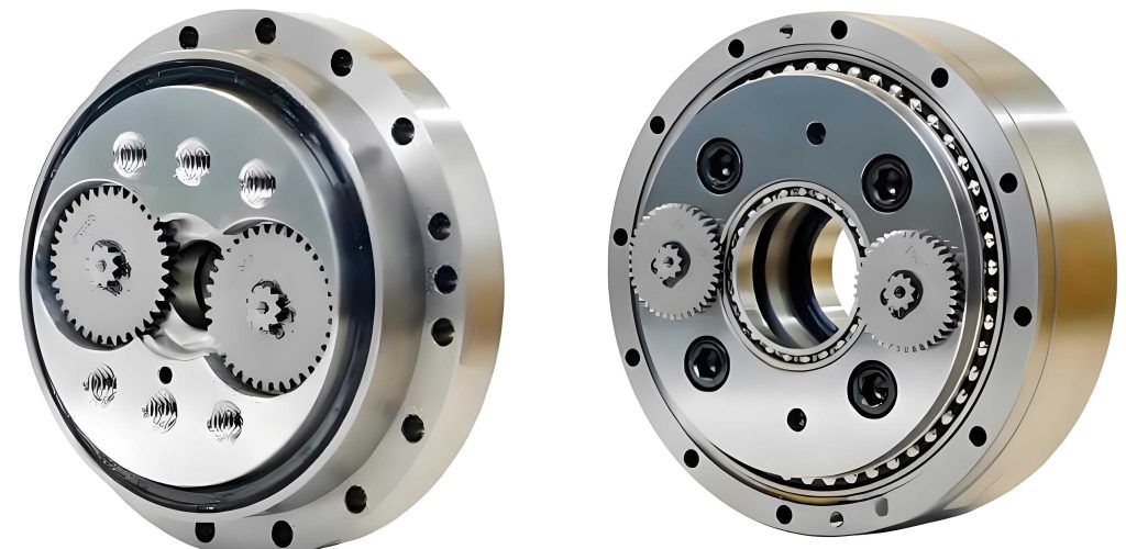
The tooth profile of the cycloidal gear in an RV reducer is derived from a curtate epicycloid curve, which ensures smooth engagement with the pin teeth. The standard tooth profile equation can be expressed in parametric form based on the geometry of the pin-cycloid system. Let $r_p$ be the radius of the pin center circle, $r_{rp}$ be the radius of the pin sleeve (or pin tooth), $a$ be the eccentricity, $z_c$ be the number of teeth on the cycloidal gear, and $z_p$ be the number of pin teeth, with $z_p = z_c + 1$. The transmission ratio $i$ is defined as $i = z_p / z_c$. The tooth profile coordinates $(x, y)$ as a function of the meshing phase angle $\phi$ are given by:
$$x = \left( r_p – r_{rp} s^{-\frac{1}{2}} \right) \cos[(1-i)\phi] – \frac{a}{r_p} \left( r_p – z_p r_{rp} s^{-\frac{1}{2}} \right) \cos(i\phi)$$
$$y = \left( r_p – r_{rp} s^{-\frac{1}{2}} \right) \sin[(1-i)\phi] + \frac{a}{r_p} \left( r_p – z_p r_{rp} s^{-\frac{1}{2}} \right) \sin(i\phi)$$
where $s = 1 + K_1^2 – 2K_1 \cos \phi$ and $K_1 = a z_p / r_p$ is the shortening coefficient. This equation describes the curtate epicycloid shape that characterizes the cycloidal gear tooth in an RV reducer. The meshing process involves multiple contact points along the tooth flank, which vary with $\phi$, leading to distributed friction heat sources. To analyze the thermal effects, I will calculate the frictional heat flux generated at these contact points.
The frictional heat flux $q$ at the meshing interface is a function of the contact stress $\sigma_p$, relative sliding velocity $v_r$, friction coefficient $f$, and energy conversion coefficient $\gamma$, expressed as:
$$q = \sigma_p v_r f \gamma$$
Here, $\gamma$ is typically taken as 0.9 to 0.95, representing the fraction of frictional energy converted into heat. For an RV reducer, determining $\sigma_p$, $v_r$, and $f$ requires detailed analysis of the contact mechanics and lubrication conditions. I will break down each parameter step by step.
First, the average contact stress $\sigma_p$ between the cycloidal gear tooth and the pin tooth can be approximated using Hertzian contact theory. Since the pin tooth has a circular profile and the cycloidal tooth has a curved profile, their contact can be modeled as two cylinders in instant contact. The maximum contact stress $\sigma_H$ and contact width $L$ are given by:
$$\sigma_H = 0.418 \sqrt{\frac{E_c P_i}{B \rho_{ei}}}$$
$$L = \sqrt{\frac{8 P_i \rho_{ei} (1 – \nu^2)}{\pi B E_c}}$$
where $P_i$ is the normal contact force at the meshing position corresponding to phase angle $\phi_i$, $E_c$ is the equivalent elastic modulus, $B$ is the tooth width, $\nu$ is Poisson’s ratio (assumed as 0.3 for steel), and $\rho_{ei}$ is the equivalent curvature radius. The average contact stress is then $\sigma_p = \frac{\pi}{4} \sigma_H$. The equivalent elastic modulus $E_c$ for steel components is $2.06 \times 10^5$ MPa. The equivalent curvature radius $\rho_{ei}$ depends on the curvature of the cycloidal tooth and the pin tooth radius. The curvature radius of the cycloidal tooth profile $\rho_{0i}$ is:
$$\rho_{0i} = \frac{(1 + K_1^2 – 2K_1 \cos \phi_i)^{\frac{3}{2}} r_p}{K_1 (1 + z_p) \cos \phi_i – (1 + z_p K_1^2)}$$
Thus, the actual curvature radius $\rho_i = \rho_{0i} + r_{rp}$, and the equivalent curvature radius is:
$$\frac{1}{\rho_{ei}} = \frac{1}{r_{rp}} – \frac{1}{\rho_i} = \frac{\rho_i – r_{rp}}{r_{rp} \rho_i} = \frac{\rho_{0i}}{r_{rp} (\rho_{0i} + r_{rp})}$$
The normal contact force $P_i$ varies with the meshing phase angle and is derived from the transmission torque. For the pin-cycloid system in an RV reducer, $P_i$ can be expressed as:
$$P_i = \frac{2.2 M_v}{K_1 z_c r_p} \cdot \frac{\sin \phi_i}{s^{\frac{1}{2}}}$$
where $M_v$ is the output torque resistance. Using these equations, I can compute $\sigma_p$ for different meshing positions. To summarize the parameters, consider a typical RV reducer model with the following values:
| Parameter | Symbol | Value |
|---|---|---|
| Number of cycloidal gear teeth | $z_c$ | 17 |
| Number of pin teeth | $z_p$ | 18 |
| Eccentricity | $a$ | 0.004 m |
| Shortening coefficient | $K_1$ | 0.5625 |
| Pin center circle radius | $r_p$ | 0.128 m |
| Pin tooth radius | $r_{rp}$ | 0.0085 m |
| Tooth width | $B$ | 0.016 m |
| Input speed | $n_H$ | 1500 rpm |
With these parameters, the variation of $\rho_{ei}$, $P_i$, and $\sigma_p$ with $\phi_i$ can be calculated. For instance, at different meshing positions along the tooth flank, the equivalent curvature radius decreases near the tooth tip, leading to higher contact stresses. The relative sliding velocity $v_r$ is another key factor in heat generation. In the RV reducer, the cycloidal gear rotates relative to the pin teeth due to the eccentric motion. Assuming the pin teeth are fixed, $v_r$ is given by:
$$v_r = \left( r_p s^{\frac{1}{2}} – r_{rp} \right) \omega_H / z_c$$
where $\omega_H = 2\pi n_H / 60$ is the angular velocity of the input shaft. The negative sign indicates opposite rotation directions, but for heat flux magnitude, absolute values are used. The friction coefficient $f$ depends on materials, surface roughness, and lubrication. Based on gear scuffing studies, $f$ can be estimated using empirical formulas:
$$f = 0.002 \left( \frac{P_{ti}}{B \times 0.001} \right)^{0.2} \cdot \left( \frac{2}{0.001 \rho_{ei} v_n \cos \alpha} \right)^{0.2} \eta^{-0.05} X$$
Here, $P_{ti}$ is the tangential load, $v_n$ is the tangential velocity, $\eta$ is the dynamic viscosity of lubricant, $\alpha$ is the pressure angle, and $X$ is the roughness factor defined as $X = 21.4 \left( \frac{S_1 + S_2}{2d} \right)^{0.25}$, with $S_1$ and $S_2$ as surface roughness values and $d$ as the pitch diameter. For typical RV reducer applications, using a lubricant with viscosity $\eta = 320 \times 10^{-6}$ m²/s, density $\rho = 900$ kg/m³, thermal conductivity $\lambda = 0.1337$ W/(m·K), and specific heat capacity $c = 900$ J/(kg·K), $f$ ranges from 0.05 to 0.1. Combining all these, the frictional heat flux $q$ distribution along the tooth flank can be derived. For example, at meshing phase angles from $\phi = 0$ to $\phi = \pi$, $q$ peaks near the middle of the contact zone due to higher contact stresses and sliding velocities.
To visualize the calculations, I present a table summarizing the frictional heat flux values at selected meshing positions for an input power of 11.25 kW (assuming output torque $M_v$ derived from power and speed). The contact zone is divided into 32 bar areas along the tooth width, as will be discussed later.
| Bar Area Index | Meshing Phase Angle $\phi_i$ (rad) | Equivalent Curvature Radius $\rho_{ei}$ (m) | Normal Force $P_i$ (N) | Average Contact Stress $\sigma_p$ (MPa) | Relative Sliding Velocity $v_r$ (m/s) | Friction Coefficient $f$ | Frictional Heat Flux $q$ (W/m²) |
|---|---|---|---|---|---|---|---|
| 0 | 0.0 | 0.0123 | 850 | 45.2 | 0.25 | 0.07 | 7.1e4 |
| 8 | 0.5 | 0.0098 | 1200 | 68.5 | 0.30 | 0.08 | 1.6e5 |
| 16 | 1.0 | 0.0075 | 1500 | 95.3 | 0.35 | 0.09 | 3.0e5 |
| 24 | 1.5 | 0.0102 | 1100 | 62.4 | 0.28 | 0.075 | 1.3e5 |
| 32 | 2.0 | 0.0130 | 800 | 40.1 | 0.22 | 0.065 | 5.8e4 |
This table illustrates how the frictional heat flux varies significantly across the tooth flank, with higher values in the central regions where contact stresses and sliding velocities are maximized. Such non-uniform heat generation directly impacts the temperature distribution in the cycloidal gear of the RV reducer.
In addition to heat generation, convective heat dissipation plays a crucial role in determining the steady-state temperature field. The cycloidal gear in an RV reducer is typically lubricated with oil, which provides cooling through forced convection. The convective heat transfer coefficient $h$ for the gear tooth surfaces can be estimated using empirical correlations for gear teeth. For laminar flow over a rotating surface, $h$ is given by:
$$h = 0.664 \lambda Pr^{\frac{1}{3}} \left( \frac{\omega}{\nu} \right)^{\frac{1}{2}}$$
where $Pr$ is the Prandtl number of the lubricant, $\omega$ is the angular velocity of the cycloidal gear rotation, and $\nu$ is the kinematic viscosity. Using the lubricant properties mentioned earlier, with $Pr = \frac{\eta c}{\lambda} \approx 500$, and $\omega = \omega_H / i$ (since the cycloidal gear rotates slower than the input), $h$ is calculated to be around 200–300 W/(m²·K) for typical RV reducer operating conditions. This convective boundary condition is applied to the tooth flanks and sides in the finite element model.
To analyze the temperature field, I employ finite element analysis (FEA) using a three-dimensional model of a single cycloidal gear tooth extracted from the full gear. This approach is valid because each tooth in the RV reducer experiences similar loading and thermal conditions. The tooth model is created based on the tooth profile equations and meshed with solid elements. The contact zone on the tooth flank is divided into multiple bar areas along the tooth width direction, each representing a discrete meshing line. The frictional heat flux calculated earlier is applied as a surface heat source to these bar areas, but with a modification to account for the intermittent nature of meshing in an RV reducer.
In the actual operation of an RV reducer, each point on the tooth flank meshes with a pin tooth only for a short duration $t_1$ during each revolution cycle $t_2$. The contact time $t_1$ depends on the contact width $L$ and sliding velocity $v_r$:
$$t_1 = \frac{L}{v_r}$$
The cycle time $t_2$ is the time for the cycloidal gear to complete one revolution relative to the pin teeth, which can be derived from the input angular velocity $\omega_H$ and the tooth difference: $t_2 = \frac{2\pi}{\omega_H} \cdot \frac{1}{z_p – 1}$. Therefore, the average frictional heat flux $\bar{q}$ applied in the FEA is scaled by the duty cycle and heat partition coefficient $\Lambda$ (taken as 0.5, assuming equal heat distribution between gear and pin):
$$\bar{q} = \frac{t_1}{t_2} q \Lambda$$
This adjustment ensures that the heat input reflects the transient meshing events in the RV reducer. For the convective boundaries, $h$ is applied to all exposed surfaces, including the tooth flanks and sides. The FEA is then solved for steady-state thermal conditions to obtain the temperature distribution.
I conducted simulations for different input power levels to assess the thermal response of the cycloidal gear in the RV reducer. The input power affects the output torque $M_v$, thereby influencing the normal force $P_i$ and frictional heat flux $q$. The table below summarizes the maximum temperature on the tooth flank for three power levels: 7.5 kW, 11.25 kW, and 15 kW, with 32 bar areas in the contact zone.
| Input Power (kW) | Output Torque $M_v$ (Nm) | Maximum Frictional Heat Flux $q_{\text{max}}$ (W/m²) | Maximum Tooth Temperature (°C) | Temperature Gradient (°C/mm) |
|---|---|---|---|---|
| 7.5 | 47.7 | 2.5e5 | 85.3 | 12.5 |
| 11.25 | 71.6 | 3.8e5 | 112.7 | 18.2 |
| 15.0 | 95.5 | 5.0e5 | 139.5 | 23.8 |
The results show that as input power increases, the maximum temperature rises significantly due to higher heat generation. However, the temperature distribution pattern remains similar, with the highest temperatures occurring near the middle of the tooth flank and decreasing towards the edges. This creates a thermal gradient that can induce thermal deformation, potentially affecting the meshing accuracy and load distribution in the RV reducer. Specifically, the temperature is higher on the contact side compared to the non-contact side, and along the tooth width, it is symmetric with a peak at the center due to poorer convective cooling in that region.
To evaluate the sensitivity of the results to the discretization of the contact zone, I varied the number of bar areas from 8 to 64 while keeping the input power at 11.25 kW. The bar areas represent the subdivision of the tooth flank along the width for applying heat flux. The following table presents the maximum and minimum temperatures on the tooth flank for different subdivisions.
| Number of Bar Areas | Maximum Temperature (°C) | Minimum Temperature (°C) | Temperature Difference (°C) |
|---|---|---|---|
| 8 | 105.2 | 65.4 | 39.8 |
| 16 | 109.8 | 63.1 | 46.7 |
| 32 | 112.7 | 61.5 | 51.2 |
| 64 | 113.5 | 60.9 | 52.6 |
As the number of bar areas increases, the temperature values converge, with changes becoming minimal beyond 32 areas. This indicates that using 32 bar areas provides a good balance between computational accuracy and efficiency for thermal analysis of the cycloidal gear in an RV reducer. The convergence behavior can be expressed mathematically: if $T(n)$ denotes the maximum temperature for $n$ bar areas, then for $n \geq 32$, the relative error $\epsilon = \frac{|T(n) – T(32)|}{T(32)}$ is less than 1%. Thus, 32 divisions are recommended for future studies on RV reducers.
The steady-state temperature field obtained from FEA reveals critical insights into the thermal behavior of the cycloidal gear. The temperature distribution is non-uniform, with hot spots at the meshing interface where friction is highest. This non-uniformity can lead to thermal expansion that distorts the tooth profile, potentially causing misalignment and increased noise in the RV reducer. Moreover, the temperature gradients along the tooth width may reduce the effective contact length, diminishing the load-carrying capacity. To mitigate these issues, design optimizations such as tooth profile modification or enhanced cooling methods could be explored based on this thermal analysis.
In conclusion, this thermal analysis of the cycloidal gear in an RV reducer highlights the importance of considering frictional heat generation and dissipation in the design process. Through detailed calculations and finite element simulations, I have shown how key parameters like input power and contact zone discretization influence the temperature field. The findings underscore that higher input powers lead to elevated temperatures, which may exacerbate thermal deformation and scuffing risks in RV reducers. Additionally, using 32 bar areas for heat flux application yields reliable results for engineering purposes. This work lays a foundation for further research aimed at improving the transmission accuracy and durability of RV reducers, such as by developing thermal management strategies or optimizing tooth geometries to minimize heat effects. Future studies could also incorporate transient thermal analysis or experimental validation to enhance the predictive capabilities for RV reducer applications.