
In the semiconductor manufacturing industry, the rapid and stable transfer of wafers is critical for maintaining high production efficiency and yield. As wafer sizes increase to 300 mm and beyond, and feature sizes shrink, the fragility of wafers demands more precise and robust handling systems. The wafer transfer robot plays a pivotal role in this process, and its end effector is the direct interface with the wafer, making its design paramount. Any deformation or vibration in the end effector can lead to wafer slippage, misalignment, or damage, disrupting the entire production line. Therefore, optimizing the end effector’s structure to enhance stiffness, reduce weight, and minimize dynamic responses is essential. In this study, I focus on the topology optimization of the end effector for a wafer transfer robot, employing computer-aided design and finite element analysis to develop a lightweight yet rigid structure that ensures reliable performance.
The end effector is typically part of a planar joint robot, such as an R-θ type, which allows radial linear motion in the horizontal plane. My design process begins with a preliminary model of the end effector, tailored for handling 300 mm wafers. Using UG software, I create a three-dimensional solid model with overall dimensions of 400 mm in length, 220 mm in width, and 5 mm in thickness. The material selected is super-hard aluminum (LC4), known for its high strength-to-weight ratio, with a Young’s modulus of 68 GPa, Poisson’s ratio of 0.33, yield strength of 680 MPa, and density of 2.7 × 10³ kg/m³. This material choice balances durability and manufacturability for the end effector.
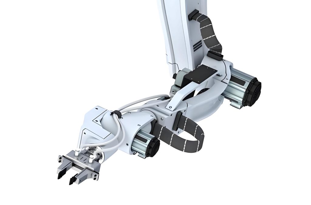
To assess the structural integrity of the initial end effector design, I perform a static structural analysis using ANSYS Workbench. The model is meshed with an automatic method, resulting in a finite element mesh that captures geometric details. Boundary conditions are applied: the end effector is fixed at the connection point to the robot’s forearm, simulating its attachment, and a pressure load of 1.28 N is applied at four contact points where the wafer rests, accounting for the wafer’s weight. Additionally, gravitational acceleration is included to reflect real-world operating conditions. The simulation reveals that the maximum total deformation occurs at the tail ends of the end effector, with a value of 0.473 mm, while the maximum von Mises stress is concentrated near the fixed connection, reaching 2.724 MPa. Although these values are within acceptable limits—the stress is well below the yield strength—they indicate areas for potential improvement. The goal is to reduce material usage without compromising performance, which leads me to explore topology optimization.
Topology optimization is a shape optimization technique that seeks the optimal material distribution within a design space, subject to constraints such as loads and boundary conditions. Unlike traditional parametric optimization, topology optimization does not rely on predefined geometric parameters; instead, it iteratively removes inefficient material based on stiffness criteria. The mathematical formulation for topology optimization can be expressed as a minimization problem:
$$
\min F(X) = \int_{\Omega} \rho(x) \, d\Omega \\
\text{subject to: } g_i(X) \leq 0, \quad i = 1, 2, \ldots, M \\
X = \{\rho(x) \mid 0 \leq \rho(x) \leq 1, \forall x \in \Omega\}
$$
Here, \( F(X) \) represents the objective function, often compliance or weight, \( \rho(x) \) is the material density at point \( x \) in the design domain \( \Omega \), and \( g_i(X) \) are constraint functions, such as volume fraction or stress limits. In ANSYS Workbench, the Topology Optimization module allows setting a target material removal percentage. For the end effector, I aim to remove 25% of the material while maintaining structural strength. To achieve this, I initially set a 50% removal target in the software, which computes the optimized material layout. The result highlights regions where material can be eliminated (shown in dark gray) and those to retain (light gray). Based on this output, I redesign the end effector by introducing two arc-shaped holes on the sides and removing excess material near the forearm connection, akin to a VCD disc design. This modified end effector model is then reconstructed in UG for further analysis.
The optimized end effector undergoes the same static structural analysis to evaluate its performance. The results show a maximum deformation of 0.464 mm and a maximum stress of 2.474 MPa, both slightly reduced compared to the initial design. Importantly, the mass decreases from 82.348 g to 69.254 g, achieving a 16% reduction in weight. This demonstrates that topology optimization successfully enhances the end effector’s efficiency by eliminating redundant material while preserving stiffness. The comparison between the initial and optimized designs is summarized in Table 1, highlighting key metrics.
| Design Type | Maximum Deformation (mm) | Maximum Stress (MPa) | Mass (g) |
|---|---|---|---|
| Initial End Effector | 0.473 | 2.724 | 82.348 |
| Optimized End Effector | 0.464 | 2.474 | 69.254 |
Beyond static analysis, dynamic behavior is crucial for the end effector, as vibrations during wafer transfer can lead to resonance with the robot arm, causing instability. To assess this, I conduct a modal analysis using ANSYS Workbench’s Modal module. Modal analysis determines the natural frequencies and mode shapes of a structure, which are vital for avoiding resonance. The equation for undamped free vibration is given by:
$$
[M]\{\ddot{u}\} + [K]\{u\} = \{0\}
$$
where \([M]\) is the mass matrix, \([K]\) is the stiffness matrix, and \(\{u\}\) is the displacement vector. Solving the eigenvalue problem \([K] – \omega^2[M] = 0\) yields natural frequencies \(\omega_i\) and corresponding mode shapes. For the optimized end effector, I extract the first six natural frequencies and their mode shapes, as listed in Table 2. The first natural frequency is 37.317 Hz, which is higher than the typical vibration frequency of robot arms (around 23 Hz). This indicates that the end effector is unlikely to resonate with the arm, ensuring stable operation. The mode shapes primarily involve translational displacements along the Z-axis and bending deformations, as illustrated in the analysis results.
| Mode Number | Natural Frequency (Hz) | Mode Shape Description |
|---|---|---|
| 1 | 37.317 | Translation along Z-axis |
| 2 | 69.625 | Translation along Z-axis |
| 3 | 139.17 | Translation along Z-axis |
| 4 | 175.97 | Translation along Z-axis |
| 5 | 346.4 | Translation along Z-axis |
| 6 | 437.76 | Second-order antisymmetric bending |
The reduction in mass achieved through topology optimization also lowers the moment of inertia, which can improve the dynamic response of the end effector. The moment of inertia \(I\) for a rigid body is defined as:
$$
I = \int_V \rho r^2 \, dV
$$
where \(\rho\) is density and \(r\) is the distance from the axis of rotation. By reducing mass, especially at distal regions, the end effector requires less torque for acceleration, enhancing energy efficiency and speed. This is particularly beneficial for wafer transfer robots that operate in high-throughput environments. Furthermore, the optimized end effector’s design, with arc-shaped holes, not only saves material but also distributes stress more evenly, reducing stress concentration factors that could lead to fatigue failure over time.
To validate the end effector’s performance under operational conditions, I consider additional factors such as thermal effects and repeated loading. Although not explicitly analyzed here, the material properties of super-hard aluminum provide good thermal stability, and the stress levels are well within the fatigue limit. The topology optimization process ensures that the end effector maintains a high stiffness-to-weight ratio, a key metric for structural efficiency. This ratio can be expressed as:
$$
\text{Stiffness-to-Weight Ratio} = \frac{E \cdot I}{m \cdot L^2}
$$
where \(E\) is Young’s modulus, \(I\) is the area moment of inertia, \(m\) is mass, and \(L\) is a characteristic length. For the optimized end effector, the reduction in mass \(m\) while preserving \(E\) and \(I\) leads to an improved ratio, contributing to better performance.
In practice, the end effector must also accommodate wafer handling mechanisms, such as sensors or grippers, but this study focuses on the structural backbone. The topology optimization approach demonstrated here can be extended to include multi-objective constraints, such as maximizing natural frequencies or minimizing compliance under multiple load cases. Future work could involve experimental validation using prototype testing or more advanced simulations like harmonic response analysis to assess vibration under external excitations.
In conclusion, the topology optimization of the end effector for wafer transfer robots yields a structurally efficient design that reduces material usage by 16% while maintaining deformation and stress within acceptable limits. The dynamic analysis confirms that the optimized end effector avoids resonance with robot arm vibrations, ensuring stable and rapid wafer transfer. This methodology highlights the value of computational tools in designing lightweight, robust components for semiconductor manufacturing. By iteratively refining the end effector through simulation-driven design, I achieve a balance between performance and cost-effectiveness, ultimately supporting the industry’s demand for higher precision and throughput. The end effector, as a critical interface, benefits from such optimizations, paving the way for more advanced wafer handling systems in the era of larger and more fragile wafers.